| 3. MANUFACTURING 3.1. Manufacturing procedures The manufacturer must ensure the competent execution of the provisions set out at the design stage by applying the appropriate techniques and relevant procedures, especially with a view to the aspects set out below. 3.1.1 Preparation of the component parts Preparation of the component parts (e.g. forming and chamfering) must not give rise to defects or cracks or changes in the mechanical characteristics likely to be detrimental to the safety of the pressure equipment. 3.1.2 Permanent joining Permanent joints and adjacent zones must be free of any surface or internal defects detrimental to the safety of the equipment. The properties of permanent joints must meet the minimum properties specified for the materials to be joined unless other relevant property values are specifically taken into account in the design calculations. For pressure equipment, permanent joining of components which contribute to the pressure resistance of equipment and components which are directly attached to them must be carried out by suitably qualified personnel according to suitable operating procedures. For pressure equipment in categories II, III and IV, operating procedures and personnel must be approved by a competent third party which, at the manufacturer's discretion, may be: To carry out these approvals the third party must perform examinations and tests as set out in the appropriate harmonised standards or equivalent examinations and tests or must have them performed. 3.1.3 Non-destructive tests For pressure equipment, non-destructive tests of permanent joints must be carried out by suitable qualified personnel. For pressure equipment of categories III and IV, the personnel must be approved by a third-party organisation recognised by a Member State pursuant to Article 13. 3.1.4 Heat treatment Where there is a risk that the manufacturing process will change the material properties to an extent which would impair the safety of the pressure equipment, suitable heat treatment must be applied at the appropriate stage of manufacture. 3.1.5 Traceability Suitable procedures must be established and maintained for identifying the material making up the components of the equipment which contribute to pressure resistance by suitable means from receipt, through production, up to the final test of the manufactured pressure equipment. 3.2. Final assessment Pressure equipment must be subjected to final assessment as described below. 3.2.1 Final inspection Pressure equipment must undergo a final inspection to assess visually and by examination of the accompanying documents compliance with the requirements of the Directive. Test carried out during manufacture may be taken into account. As far as is necessary on safety grounds, the final inspection must be carried out internally and externally on every part of the equipment, where appropriate in the course of manufacture (e.g. where examination during the final inspection is no longer possible). 3.2.2 Proof test Final assessment of pressure equipment must include a test for the pressure containment aspect, which will normally take the form of a hydrostatic pressure test at a pressure at least equal, where appropriate, to the value laid down in 7.4. For category 1 series-produced pressure equipment, this test may be performed on a statistical basis. Where the hydrostatic pressure test is harmful or impractical, other tests of a recognised value may be carried out. For tests other than the hydrostatic pressure test, additional measures, such as non-destructive tests or other methods of equivalent validity, must be applied before those tests are carried out. 3.2.3 Inspection of safety devices For assemblies, the final assessment must also include a check of the safety devices intended to check full compliance with the requirements referred to in 2.10. 3.3. Marking and labelling In addition to the CE marking referred to in Article 15, the following information must be provided: (a) for all pressure equipment: (b) depending on the type of pressure equipment, further information necessary for safe installation, operation or use and, where applicable, maintenance and periodic inspection such as: (c) where necessary, warnings fixed to the pressure equipment drawing attention to
misuse which experience has shown might occur. The CE marking and the required information must be given on the pressure equipment or on a dataplate firmly attached to it, with the following exceptions: 3.4. Operating instructions (a) When pressure equipment is placed on the market, it must be accompanied, as far as relevant, with instructions for the user, containing all the necessary safety information relating to: (b) Instructions must cover information affixed to the pressure equipment in accordance
with 3.3, with the exception of serial identification, and must be accompanied, where
appropriate, by the technical documents, drawings and diagrams necessary for a full
understanding of these instructions; 4. MATERIALS
(a) have appropriate properties for all operating conditions which are reasonably
foreseeable and for all test conditions, and in particular they should be sufficiently
ductile and tough. Where appropriate, the characteristics of the materials must comply
with the requirements of 7.5. Moreover, due care should be exercised in particular in
selecting materials in order to prevent brittle-type fracture where necessary; where for
specific reasons brittle material has to be used appropriate measures must be taken; 4.2. (a) The pressure equipment manufacturer must define in an appropriate manner the values
necessary for the design calculations referred to in 2.2.3 and the essential
characteristics of the materials and their treatment referred to in 4.1; - by using materials which comply with harmonised
standards, (c) for pressure equipment in categories III and IV, particular appraisal as referred
to in the third indent of (b) must be performed by the notified body in charge of
conformity assessment procedures for the pressure equipment. 4.3. The equipment manufacturer must take appropriate
measures to ensure that the material used conforms with the required specification. In
particular, documentation prepared by the material manufacturer affirming compliance with
a specification must be obtained for all materials. For the main pressure-bearing parts of equipment in categories II, III and IV, this must take the form of a certificate of specific product control. Where a material manufacturer has an appropriate quality-assurance system, certified by a competent body established within the Community and having undergone a specific assessment for materials, certificates issued by the manufacturer are presumed to certify conformity with the relevant requirements of this section. SPECIFIC PRESSURE EQUIPMENT REQUIREMENTS
This pressure equipment must be calculated, designed and constructed so as to avoid to minimise risks of a significant loss of containment from overheating. In particular it must be ensured, where applicable, that: (a) appropriate means of protection are provided to restrict operating parameters such
as heat input, heat take-off and, where applicable, fluid level so as to avoid any risk of
local and general overheating, 6. PIPING AS REFERRED TO IN ARTICLE 3, SECTION 1.3
(a) that the risk of overstressing from inadmissible free movement or excessive forces
being produced, e.g. on flanges, connections, bellows or hoses, is adequately controlled
by means such as support, constraint, anchoring, alignment and pre-tension; 7. SPECIFIC QUANTITATIVE REQUIREMENTS FOR CERTAIN PRESSURE EQUIPMENT
This section is an integral part of Annex 1. The provisions laid down in this section supplement the essential requirements of sections 1 to 6 for the pressure equipment to which they apply. 7.1. Allowable stresses Re/t, yield limit, indicates the value at the calculation temperature of: Rm/20 indicates the minimum value of the ultimate strength 20°C. Rm/t designates the ultimate strength at the calculation temperature. 7.1.2 The permissible general membrane stress for predominantly static loads and for temperatures outside the range in which creep is significant must not exceed the smaller of the following values, according to the material used: - in the case of ferric steel including normalised (normalised rolled)
steel and excluding fine-grained steel and specially heat-treated steel, 2/3 of Re/t and
5/12 of Rm/20 - if its elongation after rupture exceeds 30%, 2/3 of
Re/t
7.2. Joint coefficients For welded joints, the joint coefficient must not exceed the following values: If necessary, the type of stress and the mechanical and technological properties of the joint must also be taken into account. 7.3. Pressure limiting devices, particularly for pressure vessels The momentary pressure surge referred to in 2.11.2 must be kept to 10% of the maximum allowable pressure. 7.4. Hydrostatic test pressure For pressure vessels, the hydrostatic test pressure referred to in 3.2.2 must be no less than: 7.5. Material characteristics Unless other values are required in accordance with other criteria that must be taken into account, a steel is considered as sufficiently ductile to satisfy 4.1(a) if, in a tensile test carried out by a standard procedure, its elongation after rupture is no less than 14% and its bending rupture energy measured on an ISO IV test-piece is no less than 27 J, at a temperature not greater than 20°C but not higher than the lowest scheduled operating temperature.
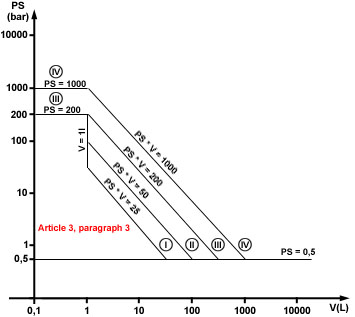
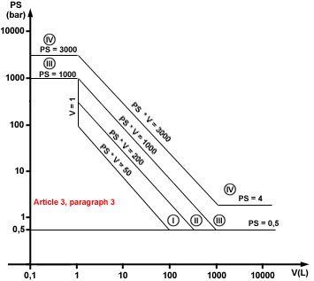
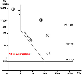
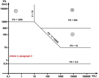
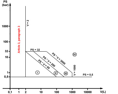
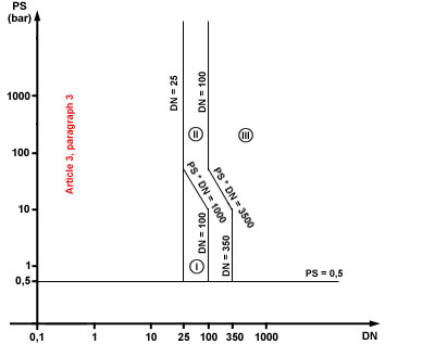
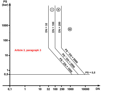
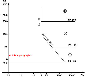
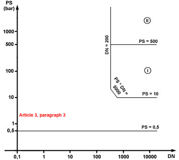
I = Module A II = Modules A1, D1, E1 III = Modules B1+D, B1+F, B+E, B+C1, H IV = Modules B+D, B+F, G, H1 2. The safety accessories defined in Article 1, Section
2.1.3, and referred to in Article 3, Section 1.4, are classified in category IV. However,
by way of exception, safety accessories manufactured for specific equipment may be
classified in the same category as the equipment they protect.
and the appropriate table for vessels or piping is to be used to determine the conformity assessment category. Where both the volume and the nominal size are considered appropriate in the second indent, the pressure accessory must be classified in the highest category. 4. The demarcation lines in the following conformity assessment tables indicate the upper limit for each category.
|